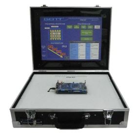
FPGA Training Kit
Model:GOTT-FPGA-77
Brand: GOTT
C/O: Malaysia
DESCRIPTION
TOP2812 development board is a TMS320F2812 DSP and EPM240T100C5 CPLD based learning and secondary development platform.
- Provides more than 20 pilot projects, with complete schematic, code, and common external interfaces can be used for individuals, companies, universities and the institute of learning and teaching tool for beginners.
- At the same time, all control signals can be leads out and the 80 I/O signals of the DSP CPLD can be used as the secondary development of the development platform.
- The board comes with EMC, EMI and thermal dissipation. It also can be interfaces with external embedded board or other products. Hence, it shorten the produce development cycle time.
RELATED INFORMATION
Complete schematic diagram (PDF format, to ensure full agreement with the PCB), to grasp a number of practical application interface
- All experiments to provide C language source code with comment
- FLASH-line methods and the programming tool for curing the user’s own procedures
- Altera download cable schematics provided
- Complimentary LCD font software development process necessary LCD display
- Quartus II 5.1 version software Hardware description language example set (dozens of program source code)
- Quartus II exclusive software proficiency essential – Chinese Quartus II software instructions
- User Manual: very detailed, including hardware, circuit analysis, test case description, CCS3.3 software Quick Start guide, TMS320F2812 chip structure and the basic system
SYSTEM RESOURCES
- DSP processor TMS320F2812, 32-bit high-speed digital fixed-point processor, the maximum operating frequency of 150MHz
- On-chip built-in 128K x 16 FLASH, using the programming can be easily cured plug-user program, FLASH can be encrypted
- On-chip built-in 18K x 16 SRAM
- On-chip built-in 4K x 16 BOOT ROM
- On-chip built-in 1K x 16 OTP ROM
- CPLD using ALTERA MAXII series EPM240T100C5N (equivalent to 8650 CPLD, the capacity is twice more than the earlier MAX series, and can be programmed at least 10 million times), interface available for download, users can write their own code
- Provides 8 LED slots for status indication
- Provides 8 independent push-button-switches
- Provides a buzzer
- Provides an 8-bit DIP switch
- Provides reset circuit to ensure reliable reset, independent reset button for manually reset
- Provides a RS-232 interface to connect PC for experiment
- Provide 1602 characters LCD interface
- DC motor control interface provided, polarized-connector design
- Provides stepper motor control interface, polarized-connector design
- Bus open, data lines, address lines, control lines, special function pin all the leads, user-friendly secondary development
- Power supply directly from an external power supply to provide a more stable and reliable
- Provide high quality independent power switch, control power, easy to operate
- Provide four fixed holes, user-friendly connection
- Physical dimensions: 17 x 11 cm
EXPERIMENT TOPICS :
DSP part:
- Experiment 1: Internal timer 0 marquees (running light) experiment
- Experiment 2: Internal timer 2 flashing lights experiment
- Experiment 3: EV Event Manager experiment
- Experiment 4: SPI digital control experiment
- Experiment 5: GPIO buzzer control experiment
- Experiment 6: RAM reads and writes outside the extended experiment
- Experiment 7: FLASH experiment by extending literacy
- Experiment 8: Key control experiment
- Experiment 9: External interrupt control experiment
- Experiment 10: ADC test
- Experiment 11: RS-232 Interface test
- Experiment 12: CAN bus interface experiments
- Experiment 13: Audio output test
- Experiment 14: DC motor control experiment
- Experiment 15: Stepper motor control experiment
- Experimental 16: 1602 character liquid crystal display experiment
- Experiment 17: FLASH the programming experiment (These pilot projects provided with C language versions of program source code with comment)
CPLD part:
- Experiment 1: DIP switch control experiment
- Experiment 2: LED test
- Experiment 3: Paragraph 3.7 of the digital control experiment decoder experiment
- Experiment 4: Crossover experiment
- Experiment 5: Key Control LED experiment
- Experiment 6: Dynamic digital control experiment
- Experiment 7: Counter experiment
- Experiment 8: State machine control experiment
- Experiment 9: Buzzer test
- Experiment 10: Experimental music
- Experiment 11: LCD display experiments (These pilot projects are using VHDL code and VHDL routines provide highlights, more than 700 commonly used routines; Verilog routines such as 135 cases for the user to learn information)
TYPICAL APPLICATION
- Teaching applications, industrial automation and control, UPS, motor control, robotics
- Frequency control, automotive, mechanical, disk drives, digital filtering
- DC motor control ACCESSORIES
- TOP2812 Development Board
- XDS100USB DSP Emulator
- 5 VDC adapter
- USB-Blaster
- 1 module of 1602 LCD
- User’s manual (CD)
- RS 232 cable
- USB cable
Manuals:
- All manuals are written in English
- Model Answer
- Teaching Manuals
General Terms:
- Accessories will be provided where applicable.
- Manuals & Training will be provided where applicable.
- Designs & Specifications are subject to change without notice.
- We reserve the right to discontinue the manufacturing of any product.
